
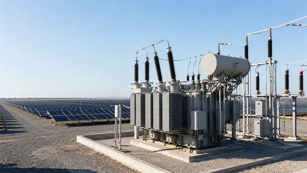
Power Transformers for Solar Power Stations
Power Transformers for Solar Power Stations
Solar power stations convert sunlight into electrical energy, but the electricity generated by photovoltaic modules cannot normally be transmitted directly to the public power grid. It must first pass through inverters, collection systems, step-up transformers and grid-connection substations.
Power transformers for solar power stations are essential components in this process. They increase the voltage generated by the photovoltaic system to a level suitable for efficient transmission and grid connection.
Correct transformer selection affects the efficiency, reliability, safety and long-term operating cost of an entire solar project. Capacity, voltage ratio, cooling method, electrical losses, harmonic conditions and installation environment must therefore be evaluated before production.
What Is a Solar Power Station Transformer?
A solar power station transformer is an electrical device used to change the voltage level within a photovoltaic power-generation system.
Solar panels generate direct current electricity. Inverters convert this direct current into alternating current, after which transformers increase the voltage for collection, transmission and connection to the utility grid.
Depending on the project architecture, a solar power station may use:
- Inverter step-up transformers
- Medium-voltage collection transformers
- Main power transformers
- Station service transformers
- Grid-connection transformers
Each transformer performs a different function and must be designed according to its location in the photovoltaic power system.
How Transformers Work in a Solar Power Station
A typical utility-scale photovoltaic power station includes several voltage-conversion stages.
- Photovoltaic modules generate direct current electricity.
- Solar inverters convert direct current into alternating current.
- Step-up transformers increase the inverter output voltage.
- Medium-voltage cables collect electricity from multiple transformer stations.
- A main transformer increases the voltage to the required grid-connection level.
- The electricity is transmitted to the utility grid through switchgear and transmission lines.
For example, an inverter may provide low-voltage AC output that is stepped up to 10kV, 20kV, 33kV or 35kV. A main substation transformer may then increase the voltage to 66kV, 110kV, 132kV, 220kV or another grid voltage.
Main Types of Transformers Used in Solar Projects
1. Inverter Step-Up Transformer
The inverter step-up transformer is installed close to the photovoltaic inverter. It increases the low-voltage AC output from the inverter to the medium-voltage level used by the solar farm collection system.
Common functions include:
- Increasing inverter output voltage
- Providing electrical isolation
- Supporting multiple inverter inputs
- Connecting the inverter station to the medium-voltage network
- Reducing transmission losses within the solar farm
2. Main Power Transformer
The main power transformer is installed in the solar power station substation. It collects power from multiple medium-voltage feeders and increases the voltage to the level required by the utility grid.
Main transformers are normally larger than inverter transformers and may be designed for high-voltage grid connections such as 66kV, 110kV, 132kV or 220kV.
3. Station Service Transformer
A station service transformer supplies electricity to auxiliary equipment within the solar power station.
Typical loads include:
- Control systems
- Lighting
- Monitoring equipment
- Heating and ventilation
- Battery charging systems
- Security and communication equipment
Why Solar Power Stations Need Special Transformer Design
Solar generation has different operating characteristics from conventional industrial loads. Transformers used in photovoltaic projects must therefore be designed around the actual generation profile and electrical conditions.
Variable Power Output
Solar generation changes according to sunlight intensity, weather, season and time of day. Transformers may experience frequent loading and unloading instead of a constant load profile.
Harmonic Current
Solar inverters use power-electronic switching devices that may introduce harmonic currents into the electrical system. Excessive harmonics can increase transformer losses, temperature and insulation stress.
High Ambient Temperature
Many solar power stations are constructed in deserts, plateaus and other areas with strong sunlight and high daytime temperatures. Transformer cooling performance must be suitable for these conditions.
Outdoor Installation
Solar transformers are commonly installed outdoors and may be exposed to dust, rain, wind, ultraviolet radiation, humidity and temperature changes.
Long Operating Life
Photovoltaic projects are generally designed for long-term operation. Transformers must therefore provide stable insulation, efficient cooling and manageable electrical losses throughout the project lifecycle.
Oil-Immersed or Dry-Type Transformer?
Both oil-immersed and dry-type transformers can be used in solar power projects, but they are suited to different installation conditions.
Oil-Immersed Transformers
Oil-immersed transformers are commonly selected for outdoor and high-capacity solar projects because they provide:
- Effective heat dissipation
- High voltage and capacity options
- Reliable outdoor operation
- Good overload capability when properly designed
- Competitive cost for utility-scale projects
Dry-Type Transformers
Dry-type transformers may be suitable for indoor inverter rooms or projects with strict fire-safety requirements. Their advantages include:
- No insulating oil
- Lower risk of oil leakage
- Reduced fire and environmental concerns
- Suitability for indoor installation
- Relatively simple routine maintenance
The final choice should consider voltage, capacity, installation location, fire-safety rules, environmental conditions and project budget.
Important Transformer Specifications
Rated Capacity
Transformer capacity should match the maximum inverter output, expected generation profile, operating reserve and project expansion plan.
Capacity selection should consider:
- Total installed photovoltaic capacity
- Inverter output capacity
- Power factor
- Expected overload conditions
- Ambient temperature
- Installation altitude
- Future capacity expansion
Voltage Ratio
The voltage ratio must match the inverter output, medium-voltage collection system and utility grid.
Common solar-project voltage levels may include:
- 0.4kV or 0.8kV inverter output
- 10kV, 20kV, 33kV or 35kV collection voltage
- 66kV, 110kV, 132kV or 220kV grid-connection voltage
The actual voltage combination depends on the inverter design, local grid standards and overall substation configuration.
Vector Group
The transformer vector group determines winding connection, phase displacement, grounding characteristics and harmonic behavior.
It must be coordinated with the inverter, switchgear, protection system and utility grid requirements.
Short-Circuit Impedance
Transformer impedance affects short-circuit current, voltage drop and parallel operation. It must be selected according to the electrical system design rather than treated as an independent parameter.
Tap-Changing Method
Solar transformers may use an off-circuit tap changer or an on-load tap changer, depending on the voltage-regulation requirements.
- Off-circuit tap changer: adjusted when the transformer is de-energized.
- On-load tap changer: adjusts the voltage ratio while the transformer remains in operation.
Main grid-connection transformers are more likely to use on-load voltage regulation when the project requires continuous control of the outgoing voltage.
Cooling Method
Common cooling methods for oil-immersed solar transformers include:
- ONAN: Oil Natural Air Natural
- ONAF: Oil Natural Air Forced
- OFAF: Oil Forced Air Forced
Cooling selection depends on transformer capacity, load profile, ambient temperature and installation environment.
Electrical Losses and Project Efficiency
Transformer efficiency is particularly important in solar power stations because even small losses accumulate over years of operation.
The two principal transformer losses are:
- No-load loss: generated in the core whenever the transformer is energized.
- Load loss: generated mainly in the windings and increases with transformer loading.
Solar transformers may remain energized during periods of low generation or no generation. For this reason, no-load loss should receive careful attention during product selection.
When comparing transformer options, buyers should evaluate:
- No-load loss
- Load loss
- Expected annual operating profile
- Cooling-system energy consumption
- Electricity value over the project lifetime
- Initial equipment cost
A transformer with a lower purchase price may not provide the lowest total lifecycle cost.
Environmental Conditions to Confirm
Solar power stations are often built in demanding environments. The transformer manufacturer should receive accurate site information before completing the design.
Important conditions include:
- Maximum and minimum ambient temperature
- Installation altitude
- Solar radiation intensity
- Humidity
- Dust and sand levels
- Salt pollution in coastal locations
- Wind speed
- Rainfall and snow
- Seismic requirements
- Flooding risk
High-Altitude Solar Projects
At high altitude, lower air density reduces cooling performance and electrical insulation strength. The transformer may require adjusted insulation clearances, cooling capacity or derating.
Desert Solar Projects
Desert projects may expose transformers to high temperature, strong ultraviolet radiation, sand and rapid temperature changes. Sealing, surface coating, radiator design and air filtration around auxiliary equipment should be considered.
Coastal Solar Projects
Salt and humidity can accelerate corrosion. Coastal transformers may require enhanced anti-corrosion treatment, suitable enclosure protection and carefully selected external hardware.
Protection and Monitoring Requirements
A solar power station transformer should be integrated with the project protection, control and monitoring system.
Common protection and monitoring options include:
- Buchholz relay
- Pressure-relief device
- Oil-level indicator
- Oil temperature indicator
- Winding temperature indicator
- Overcurrent protection
- Differential protection
- Ground-fault protection
- Surge protection
- Online dissolved-gas monitoring
- Remote alarm and trip contacts
- Communication interfaces
The final configuration should follow the transformer capacity, voltage level, utility requirements and project protection philosophy.
How to Select a Transformer for a Solar Power Station
Step 1: Confirm the Solar Generation Capacity
Identify the total photovoltaic capacity, inverter capacity, expected maximum AC output and expansion plan.
Step 2: Define the Electrical Architecture
Confirm the inverter output voltage, medium-voltage collection level and final grid-connection voltage.
Step 3: Analyze the Load Profile
Review daily and seasonal generation patterns, expected overload conditions and periods when the transformer remains energized without significant load.
Step 4: Check Harmonic Conditions
Obtain harmonic information from the inverter supplier and evaluate whether the transformer requires additional thermal capacity or a special winding design.
Step 5: Confirm Site Conditions
Provide accurate altitude, temperature, humidity, dust, pollution and seismic data to the transformer manufacturer.
Step 6: Select the Cooling System
Choose ONAN, ONAF or another cooling method according to the rated capacity, site temperature and operating profile.
Step 7: Evaluate Losses
Compare no-load loss, load loss and projected lifecycle energy cost instead of considering only the initial transformer price.
Step 8: Finalize Protection and Monitoring
Specify all protection relays, temperature indicators, oil monitoring devices, alarms and communication interfaces.
Customization Options
Power transformers for solar power stations can be customized according to the grid and engineering requirements.
- Rated capacity
- Primary and secondary voltage
- Rated frequency
- Vector group
- Short-circuit impedance
- Tap-changing range
- Off-circuit or on-load tap changer
- Cooling method
- Winding material
- Radiator arrangement
- Terminal and bushing direction
- Protection and monitoring equipment
- Noise requirements
- Anti-corrosion treatment
- Applicable standards
- Export packaging
- Technical documentation
Information Required for a Quotation
To obtain an accurate technical proposal and quotation, buyers should provide:
- Solar power station capacity
- Transformer rated capacity
- Primary voltage
- Secondary voltage
- Rated frequency
- Number of phases
- Vector group
- Required impedance
- Tap-changing requirements
- Cooling method
- Inverter type and harmonic information
- Installation altitude
- Ambient temperature range
- Pollution and environmental conditions
- Applicable standards
- Protection and monitoring requirements
- Destination country
- Required quantity
- Expected delivery schedule
Providing a single-line diagram, transformer specification and inverter technical data will help the manufacturer prepare a more accurate design.
Frequently Asked Questions
What type of transformer is used in a solar power station?
Solar power stations commonly use inverter step-up transformers, medium-voltage collection transformers, main grid-connection transformers and station service transformers.
What does a solar step-up transformer do?
It increases the AC voltage produced by the solar inverter to the medium-voltage or high-voltage level required for collection and grid connection.
Can oil-immersed transformers be used in solar farms?
Yes. Oil-immersed transformers are widely used in outdoor and utility-scale solar projects because they support high capacities, effective cooling and multiple voltage levels.
Are dry-type transformers suitable for solar projects?
Yes. Dry-type transformers may be suitable for indoor installations, inverter rooms and projects with strict fire-safety or environmental requirements.
How is solar transformer capacity selected?
Capacity should be based on inverter output, total generation capacity, power factor, overload requirements, site temperature, altitude and future expansion.
Why are transformer losses important in solar projects?
Electrical losses reduce the energy delivered to the grid. Because solar projects operate for many years, small efficiency differences can produce significant lifecycle costs.
Do solar transformers need special harmonic design?
They may require harmonic evaluation because power-electronic inverters can introduce harmonic current. The final design should be based on inverter data and system studies.
Can the voltage ratio be customized?
Yes. Primary voltage, secondary voltage, tap range and grid-connection voltage can be designed according to the solar project.
Can solar transformers be used at high altitude?
Yes, but altitude must be considered during design because reduced air density affects cooling and external insulation performance.
What documents are needed for transformer selection?
Useful documents include the single-line diagram, transformer specification, inverter datasheet, harmonic report, site-condition data and utility grid requirements.
Conclusion
Power transformers for solar power stations connect photovoltaic generation equipment to medium-voltage collection systems and public power grids. Their performance directly affects project efficiency, voltage stability, safety and long-term operating cost.
A suitable solar power transformer should be selected according to generation capacity, voltage ratio, load profile, harmonic conditions, cooling requirements, electrical losses and installation environment.
Providing complete electrical parameters and site information allows the transformer manufacturer to develop a reliable solution for inverter stations, solar substations and utility-scale photovoltaic projects.
