
Transformer Impedance Explained
Transformer impedance is one of the most important technical parameters when selecting a power transformer. It directly affects short-circuit current, voltage drop, system protection, transformer parallel operation and the stability of the electrical network.
Although impedance is normally shown as a simple percentage on the transformer nameplate, its influence extends across the entire power-distribution system. Selecting an unsuitable impedance value can lead to excessive fault current, unacceptable voltage variation or poor load sharing between transformers.
This guide explains transformer impedance in practical terms and shows what engineers, project contractors and equipment buyers should consider before placing an order.
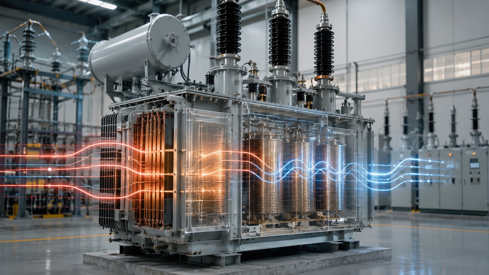
Transformer Impedance Explained Meaning and Selection Guide
What Is Transformer Impedance?
Transformer impedance is the internal opposition that limits current flow through the transformer. It includes the combined effect of winding resistance and leakage reactance.
In transformer specifications, impedance is normally expressed as a percentage and may also be called:
- Percentage impedance
- Short-circuit impedance
- Impedance voltage
- Transformer impedance voltage
- Uk percentage
For example, a transformer nameplate may show:
- Impedance: 4%
- Short-circuit impedance: 6%
- Uk: 10.5%
These descriptions generally refer to the voltage required to circulate rated current through the transformer when one winding is short-circuited under controlled test conditions.
What Does Transformer Impedance Percentage Mean?
The impedance percentage indicates how much of the rated primary voltage is required to produce rated current when the secondary winding is short-circuited.
For example, if a transformer has an impedance of 6%, approximately 6% of its rated voltage is required to circulate full-load current during the short-circuit impedance test.
A lower impedance allows more fault current to flow. A higher impedance limits fault current more effectively but may cause greater voltage drop during normal operation.
Why Is Transformer Impedance Important?
1. It Limits Short-Circuit Current
The transformer impedance limits the current that can flow when a short circuit occurs on the secondary side.
A transformer with lower impedance generally permits higher short-circuit current, while a transformer with higher impedance reduces the available fault current.
This affects the selection of:
- Circuit breakers
- Busbars
- Switchgear
- Cables
- Protection relays
- Current transformers
- Downstream electrical equipment
2. It Affects Voltage Regulation
Transformer output voltage changes as the connected load increases or decreases. Internal impedance contributes to this voltage variation.
A higher impedance may produce a larger voltage drop under heavy load. This can be important in systems supplying motors, industrial machinery, data centers and other voltage-sensitive equipment.
3. It Influences Parallel Operation
When two or more transformers operate in parallel, their impedance values must be properly matched.
If the impedance values are significantly different, the transformers may not share the load evenly. One transformer may become overloaded while another remains below its rated capacity.
4. It Affects Motor Starting
Large motors draw high current during startup. Transformer impedance contributes to the voltage drop that occurs during this period.
If impedance is too high, motor-starting voltage may fall below an acceptable level. This can result in:
- Slow motor acceleration
- Failure to start
- Contactor dropout
- Process interruption
- Excessive heating
5. It Affects Protection Coordination
Fault-current calculations depend heavily on transformer impedance. Protection engineers use this information to determine breaker ratings, relay settings and system selectivity.
Transformer Impedance and Short-Circuit Current
The available short-circuit current on the transformer secondary side is approximately inversely related to the transformer impedance percentage.
A simplified estimate can be expressed as:
Short-circuit current multiplier = 100 ÷ impedance percentage
For example:
- A 4% impedance transformer may allow approximately 25 times rated current.
- A 5% impedance transformer may allow approximately 20 times rated current.
- A 6% impedance transformer may allow approximately 16.7 times rated current.
- A 10% impedance transformer may allow approximately 10 times rated current.
These are simplified transformer-terminal estimates. Actual system fault current also depends on:
- Utility-grid impedance
- Cable impedance
- Generator contribution
- Motor contribution
- Busbar impedance
- System grounding
- Fault location
Example of Transformer Impedance Calculation
Assume a transformer has:
- Rated capacity: 1,000kVA
- Secondary voltage: 400V
- Three-phase output
- Impedance: 5%
The rated secondary current is approximately:
Rated current = 1,000,000 ÷ (1.732 × 400)
The result is approximately:
1,443A
The estimated short-circuit current at the transformer terminals is:
1,443 × (100 ÷ 5) = approximately 28,860A
Therefore, the transformer may contribute approximately 28.9kA of short-circuit current at its secondary terminals under simplified conditions.
This example should not replace a complete short-circuit study, especially for high-voltage, industrial or utility projects.
Low Impedance vs High Impedance
Low Transformer Impedance
Advantages may include:
- Lower voltage drop under load
- Better voltage performance during motor starting
- Improved voltage regulation
- Higher ability to support sudden load changes
Possible disadvantages include:
- Higher short-circuit current
- Higher switchgear interrupting requirements
- Greater mechanical stress during faults
- Higher downstream equipment ratings
High Transformer Impedance
Advantages may include:
- Lower short-circuit current
- Reduced breaker interrupting requirements
- Lower mechanical stress during faults
- Improved fault-current limitation
Possible disadvantages include:
- Greater voltage drop under load
- More severe voltage reduction during motor starting
- Possible reduction in system voltage stability
- Higher reactive voltage drop
Typical Transformer Impedance Values
Transformer impedance depends on rated capacity, voltage level, winding design and applicable standards.
Typical ranges may include:
- Small distribution transformers: approximately 3%–6%
- Medium-sized distribution transformers: approximately 4%–8%
- Large industrial transformers: approximately 6%–10%
- High-voltage power transformers: often 8%–18% or project-specific
- Special fault-limiting transformers: higher values may be specified
These values are general references only. The correct impedance must be determined by the electrical-system design and project specification.
What Determines Transformer Impedance?
Transformer impedance is influenced mainly by winding geometry and conductor arrangement.
Important design factors include:
- Distance between primary and secondary windings
- Winding height
- Winding diameter
- Conductor size
- Number of winding turns
- Core and coil arrangement
- Leakage magnetic flux
- Winding resistance
- Rated capacity
- Voltage class
Transformer manufacturers adjust these design parameters to achieve the required impedance while maintaining acceptable losses, temperature rise and mechanical strength.
Transformer Impedance in Parallel Operation
Transformers operating in parallel should have compatible electrical characteristics.
Important conditions include:
- Equal or compatible voltage ratios
- Matching vector groups
- Same phase sequence
- Similar impedance percentages
- Similar impedance angle
- Compatible tap positions
- Suitable capacity ratio
When transformer impedance values are different, load sharing is approximately inversely proportional to impedance.
The transformer with lower impedance tends to carry more load. If the difference is too large, that transformer may become overloaded before the total combined transformer capacity is reached.
Example of Unequal Load Sharing
Consider two transformers with the same voltage ratio and rated capacity:
- Transformer A impedance: 5%
- Transformer B impedance: 6%
Transformer A has lower impedance and will normally carry a greater share of the total load.
This is why parallel transformers should be specified with closely matched impedance values and manufacturing tolerances.
Impedance and Transformer Voltage Drop
Transformer impedance causes internal voltage drop as load current flows through the windings.
The actual voltage drop depends on:
- Load current
- Load power factor
- Transformer resistance
- Transformer reactance
- Impedance percentage
- Tap position
Inductive loads generally produce a greater voltage drop than loads operating at unity power factor.
For voltage-sensitive projects, transformer impedance should be evaluated together with cable voltage drop, motor starting and downstream distribution conditions.
Impedance and Transformer Losses
Transformer impedance and transformer losses are related but are not the same parameter.
Transformer losses mainly include:
- No-load loss: generated primarily in the core.
- Load loss: generated mainly in the windings and structural components.
The resistance component of impedance contributes to load loss, while the reactance component mainly affects voltage regulation and fault-current limitation.
A transformer should not be selected based only on impedance. Efficiency, load losses, temperature rise and lifecycle operating cost should also be evaluated.
How Transformer Impedance Is Tested
Transformer impedance is normally measured during a short-circuit test.
A simplified test procedure includes:
- One transformer winding is short-circuited.
- A reduced voltage is applied to the other winding.
- The voltage is gradually increased until rated current flows.
- The applied voltage is recorded.
- The result is expressed as a percentage of rated voltage.
The test also helps determine load loss and the resistive and reactive components of transformer impedance.
How to Select the Correct Transformer Impedance
Step 1: Calculate the Available Fault Current
Determine the maximum permitted short-circuit current at the transformer secondary terminals and downstream switchgear.
Step 2: Check Switchgear Ratings
Confirm that circuit breakers, busbars and cables can withstand and interrupt the calculated fault current.
Step 3: Evaluate Voltage Regulation
Check the expected transformer voltage drop at full load and under different power-factor conditions.
Step 4: Analyze Motor Starting
For projects with large motors, calculate the voltage dip during direct-on-line, soft-start or variable-frequency-drive operation.
Step 5: Review Parallel Operation
If the transformer will operate in parallel with another unit, confirm matching voltage ratio, vector group, impedance and tap settings.
Step 6: Coordinate Protection
Use the selected impedance value in the short-circuit and protection-coordination studies.
Step 7: Confirm the Manufacturer’s Tolerance
Specify the required impedance and permitted manufacturing tolerance in the technical agreement.
Common Mistakes When Selecting Transformer Impedance
- Selecting the lowest possible impedance without checking fault current
- Selecting high impedance only to reduce breaker cost
- Ignoring voltage drop during motor starting
- Using transformers with significantly different impedance in parallel
- Confusing impedance with transformer efficiency
- Ignoring utility-grid fault contribution
- Failing to include impedance tolerance in the technical specification
- Copying impedance values from an unrelated project
Information Required from the Buyer
To determine an appropriate transformer impedance, buyers should provide:
- Rated transformer capacity
- Primary voltage
- Secondary voltage
- Rated frequency
- System short-circuit level
- Required impedance percentage
- Maximum downstream fault-current limit
- Switchgear interrupting rating
- Load characteristics
- Motor sizes and starting methods
- Parallel-operation requirements
- Vector group
- Tap-changing range
- Applicable standards
- Utility or consultant specification
A single-line diagram and short-circuit study are particularly useful when confirming the final transformer impedance.
Frequently Asked Questions
What does 6% transformer impedance mean?
It means approximately 6% of the rated voltage is required to circulate rated current when the opposite winding is short-circuited during the impedance test.
Is lower transformer impedance better?
Not always. Lower impedance improves voltage regulation but increases short-circuit current. The correct value depends on the electrical-system design.
Does higher impedance reduce fault current?
Yes. Higher transformer impedance generally reduces the short-circuit current available at the secondary terminals.
Does transformer impedance affect voltage drop?
Yes. Higher impedance normally causes a larger voltage drop when the transformer supplies load, especially at a low power factor.
Can transformers with different impedance values operate in parallel?
They may operate in parallel if other electrical conditions are satisfied, but unequal impedance can cause uneven load sharing. Closely matched impedance values are recommended.
Where can I find the impedance value?
It is normally shown on the transformer nameplate, technical datasheet, routine test report or factory test certificate.
Is transformer impedance the same as resistance?
No. Impedance includes both resistance and reactance. Resistance mainly produces heat, while reactance is associated with leakage magnetic flux.
Does transformer capacity affect impedance?
Yes. Transformer capacity, voltage level and winding design influence the impedance value. Larger transformers often have different impedance requirements from small distribution units.
Can transformer impedance be customized?
Yes. Manufacturers can design transformers to meet a specified impedance range, provided that the requirement is technically practical and coordinated with other performance parameters.
Why does impedance have a manufacturing tolerance?
Small variations in winding dimensions, conductor positioning and manufacturing processes can affect the final measured impedance. The permitted tolerance should be defined by the applicable standard and purchase specification.
Conclusion
Transformer impedance is a critical parameter that influences short-circuit current, voltage regulation, motor starting, protection coordination and parallel transformer operation.
A low impedance value may improve voltage performance but increase fault-current levels. A high impedance value may limit fault current but cause greater voltage drop. Therefore, there is no single impedance value suitable for every transformer project.
The final transformer impedance should be selected through system calculations and coordinated with transformer capacity, grid conditions, switchgear ratings, load characteristics and protection requirements.
